Shiners: When the Screws Miss the Studs – and What to do About Them

By Guy Long and Paul Grahovac

The Master Specification of the Air Barrier Association of America (ABAA) provides: “Perform the air leakage test and water penetration test of mock-up after installation of all fasteners for cladding and trim.”

Unfortunately, ABAA and its manufacturer, specifier, consultant and contractor members have found that what happens with the fasteners in a mock-up is often not the same as what happens in the overall project. 

That’s why an ABAA newsletter reported on a joint ABAA and U. S. Department of Energy research project where six rows of fasteners were installed into exterior gypsum sheathing after an air and water-resistive barrier system had been installed, and the specimen was then subjected to a pressure differential and sprayed with water. Each row of fasteners was installed differently – including missed stud with fastener left in place and missed stud with fastener removed.

The results of the testing are not yet available, yet the industry continues to experience the problem -- and a need for a solution.

In 2014, building enclosure consultant Karl A. Schaack, RRC, PE, wrote an article titled, “Fasteners and Self-Sealability of Weather-Resistive Barriers” in INTERFACE, The Technical Journal of the International Institute of Building Enclosure Consultants.

He writes: “Unlike securement into a plywood substrate that has historically been used in exterior wall construction (particularly for plaster applications), when a fastener is installed into and through gypsum sheathing that does not penetrate into a sound substrate, the fastener continues to spin, reaming out the hole. The density of gypsum sheathing is not substantial enough to allow the fastener to “bite” and attain adequate compression against the WRB material (either liquid-applied or self-adhering sheets); consequently, the fastener hole becomes enlarged as the fastener spins. With a plywood backup, a fastener could be placed in almost any location to achieve adequate compression, even though it may not penetrate into a framing member. In addition, variabilities introduced during field installation of fasteners can create conditions that result in inadequate application. For example, if the fastener or other element is not installed straight and true or is installed over-aggressively, the WRB can be damaged, which can result in water leakage, even if the fastener is driven into a framing member.

Damage to the WRB may also occur due to poorly installed fasteners, removed fasteners, or fastener length for attachment of cladding components exceeding the depth of the sub-framing member (i.e., hat channel). When light-gauge steel framing, sub-girts, hats, and masonry ties are installed on top of the WRB, and fasteners are secured into the backup structure, the rigid steel sub-framing or steel tie typically cannot conform to uneven areas in the substrate, and the fastener cannot develop full compression against the WRB to achieve an adequate seal (Photo 5).

Some manufacturers of liquid-applied WRBs recommend installation of cut strips of self-adhering sheet between the steel girt or tie and the WRB to aid in achieving an adequate seal at fastener penetrations (Diagram 2).

Additionally, the heads of fasteners may need to be treated with a dollop of compatible sealant or trowelable version of the liquid membrane to provide a more suitable seal (Diagram 3 and Photo 6). Another practice could include setting the masonry tie in “wet” liquid-applied WRB when securing to the substrate."

In the case study that follows, the architect changed their specification requiring the screws to be left in to one calling for the fluid-applied hole sealing system that is described. The interior drywall was going up before the lath, so the shiners could not be seen or sealed from the inside. The exterior sealing method described below has significant utility even if the interior drywall is not up. As anyone who has done it knows, finding shiners and sealing from the inside is highly problematic. The space is often poorly lit, and the fasteners are usually very close to the studs. With several installers outside, more than one inside spotter is needed to avoid delaying the installation of the batt insulation and drywall.

Four samples were overnighted to the testing facility in Santa Rosa Beach Florida. These mockup boards were to be air and water tested to provide a suitable solution to the problem of missing the stud with the attachment of the Structalath. See Figure 1.

Figure 1
Figure 1
Figure 2. Back side of mock-up.
Figure 3.
Fastener missed stud on exterior of drainage mat.
Figure 3. Fastener missed stud on exterior of drainage mat.
Figure 4.
Fastener missing stud interior side of sheathing.
Figure 4. Fastener missing stud interior side of sheathing.
Figure 5.
PROSOCO R-Guard Cat 5 used to seal fastener hole after the fastener had been removed.
Figure 5. PROSOCO R-Guard Cat 5 used to seal fastener hole after the fastener had been removed.
Figure 6.
Injector syringe delivering sealing solution. Cat 5 delivered through tubing.
Figure 6. Injector syringe delivering sealing solution. Cat 5 delivered through tubing.
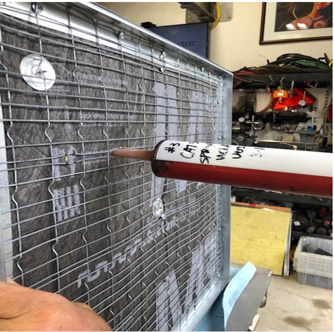
Figure 7.  Diagonally cut delivery tube attached to the syringe filled with Cat 5.
Figure 7. Diagonally cut delivery tube attached to the syringe filled with Cat 5.
Figure 8. Injector kit with syringe, attachment and end cap with tubing cut diagonally to insert into open hole in sheathing.
Figure 9. 
Sealing solution (Cat 5) being injected through hole in sheathing. 
Syringe and diagonally cut tubing are turned 90° cutting into the open hole.
Figure 9. Sealing solution (Cat 5) being injected through hole in sheathing. Syringe and diagonally cut tubing are turned 90° cutting into the open hole.
Figure 10.
Test of multiple drilled holes in mock-up.
Figure 10. Test of multiple drilled holes in mock-up.
Figure 11.
Disassembly of mockup.
PROSOCO R-Guard AirDam tested on left side of mockup. Cat 5 tested on right side of mockup.
Figure 11. Disassembly of mockup. PROSOCO R-Guard AirDam tested on left side of mockup. Cat 5 tested on right side of mockup.
Figure 12.
Structalath removed from mockup to exhibit AirDam residue on left side hole repairs and Cat 5 rundown on drainage mat.
Figure 12. Structalath removed from mockup to exhibit AirDam residue on left side hole repairs and Cat 5 rundown on drainage mat.
Figure 13.
Thermafiber insulation.
Figure 13. Thermafiber insulation.
Figure 14.
Lath grid laid over insulation to identify means of sealing material used on both sides of the mockup.
Figure 14. Lath grid laid over insulation to identify means of sealing material used on both sides of the mockup.
Figure 15.
Insulation removed to exhibit sealant residue after holes were filled with either AirDam or Cat 5.
Figure 15. Insulation removed to exhibit sealant residue after holes were filled with either AirDam or Cat 5.
Figure 16.
Baseline air flow test starts a 0 by means of the use of a rilem tube as noted in the next slide.
Figure 16. Baseline air flow test starts a 0 by means of the use of a rilem tube as noted in the next slide.
Figure 17.
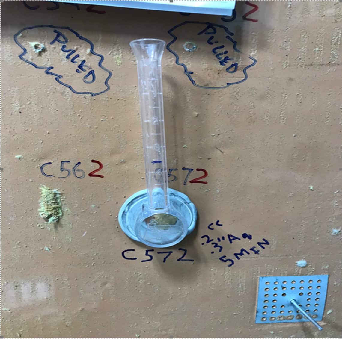
This illustrates the pipe-like apparatus designed for vertical surfaces. Its flat, circular brim (at the bottom end of the pipe) is affixed to the sheathing surface by interposing a piece of putty. The open, bottom end of the pipe has an area of 4.9 cm². The vertical tube is graduated from 0 to 5 mL with each gradation representing an increment of 0.5. The total height of the column of water applied to the surface, measured from the center point of the flat, circular brim to the topmost gradation, is 12 cm.  This corresponds to a pressure of 1177.2 pascals (approximately 0.17psi), or a dynamic wind pressure of 157.8 kilometers per hour (approximately 98.1 mph).
Figure 17. This illustrates the pipe-like apparatus designed for vertical surfaces. Its flat, circular brim (at the bottom end of the pipe) is affixed to the sheathing surface by interposing a piece of putty. The open, bottom end of the pipe has an area of 4.9 cm². The vertical tube is graduated from 0 to 5 mL with each gradation representing an increment of 0.5. The total height of the column of water applied to the surface, measured from the center point of the flat, circular brim to the topmost gradation, is 12 cm. This corresponds to a pressure of 1177.2 pascals (approximately 0.17psi), or a dynamic wind pressure of 157.8 kilometers per hour (approximately 98.1 mph).
Figure 18.
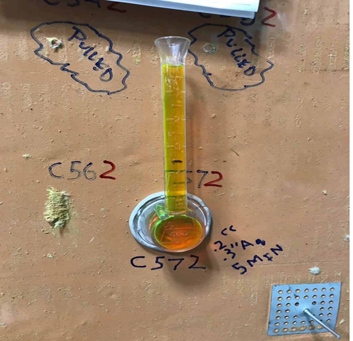
Water with fluorescein dye coming through and around the fastener using a black light to illuminate the dye. The rilem tube was filled up to the top and it ran out the backside of the sheathing as quick as we poured it into the tube indicating significant air/water leakage would occur.
Figure 18. Water with fluorescein dye coming through and around the fastener using a black light to illuminate the dye. The rilem tube was filled up to the top and it ran out the backside of the sheathing as quick as we poured it into the tube indicating significant air/water leakage would occur.
Figure 19.
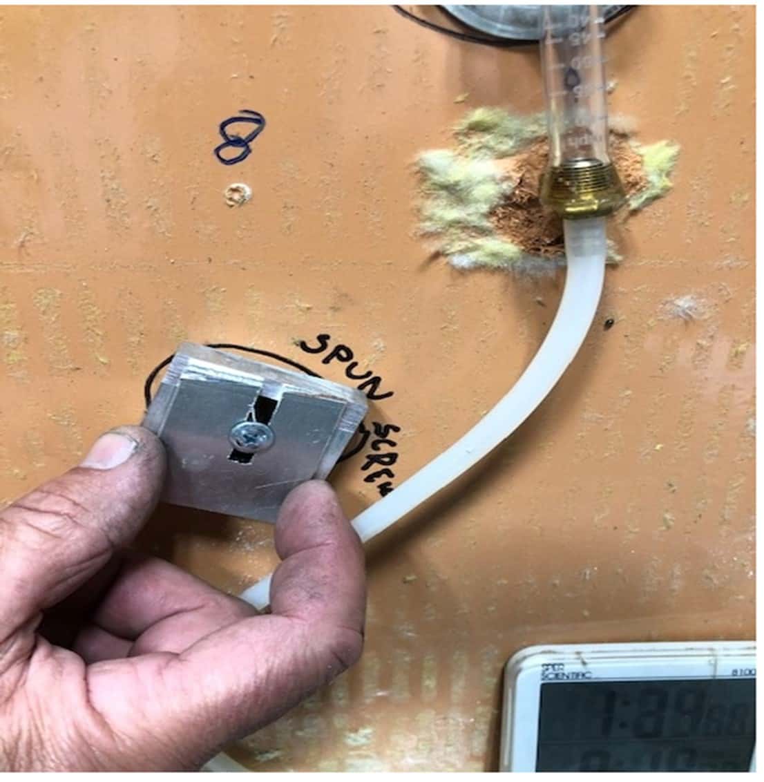
We demonstrated the wallowing out of the fastener with this devise that allowed the fastener to freely spin within the sheathing.
Figure 19. We demonstrated the wallowing out of the fastener with this devise that allowed the fastener to freely spin within the sheathing.
Figure 20.
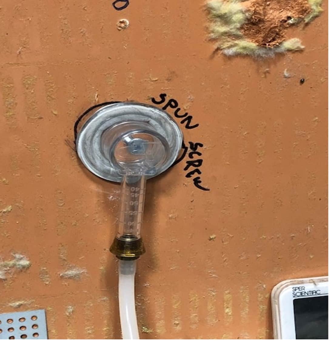
When the spun fastener was tested for air leakage. One (1) cc of air flowed directly through the opening every second with the fastener still intact. For that reason, we choose to remove the fastener and seal the open hole.
Figure 20. When the spun fastener was tested for air leakage. One (1) cc of air flowed directly through the opening every second with the fastener still intact. For that reason, we choose to remove the fastener and seal the open hole.
Figure 21.
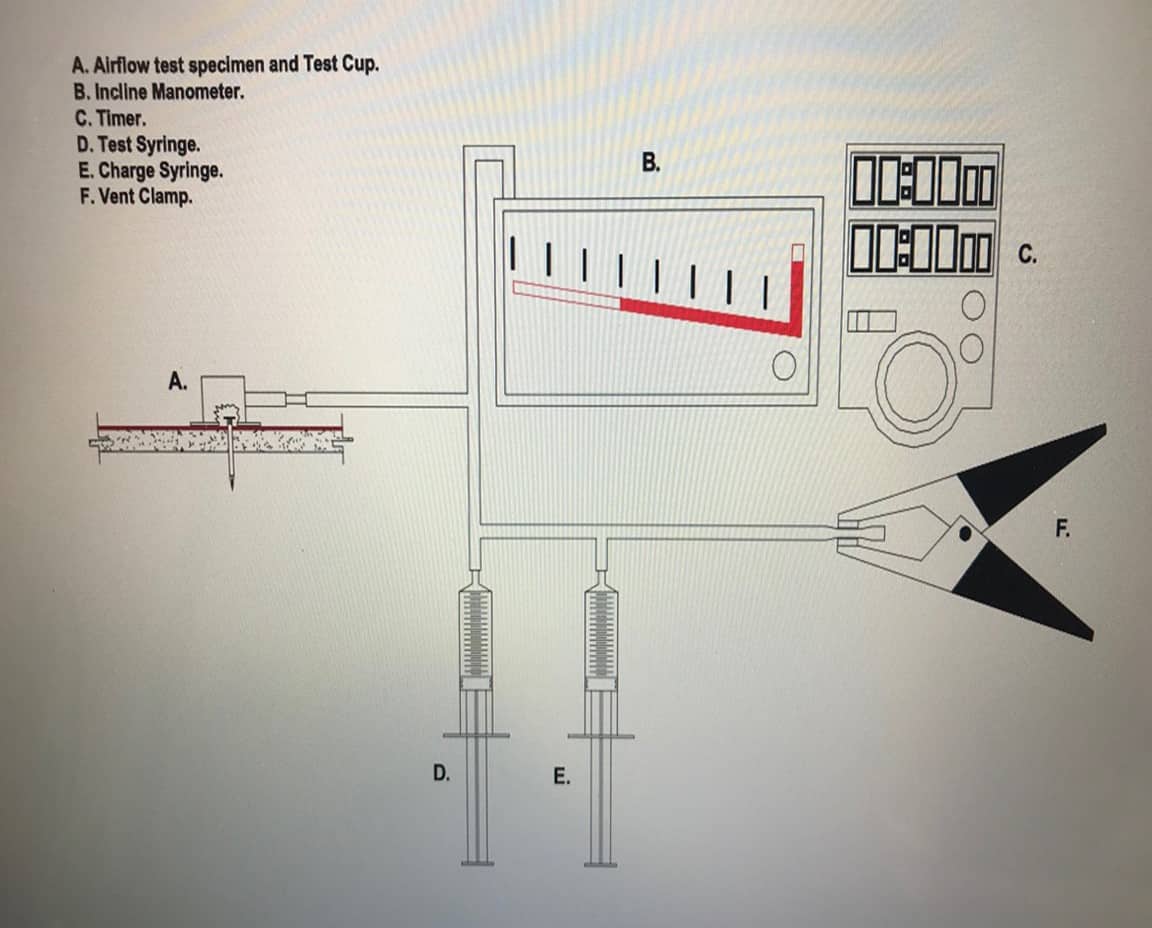
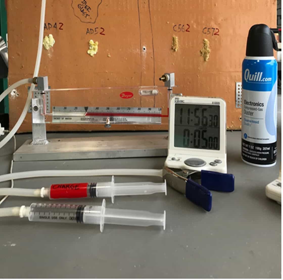
This Rosetta testing device delivers a measured air pressure of .03 Au during a 5-minute period.
Figure 21. This Rosetta testing device delivers a measured air pressure of .03 Au during a 5-minute period.
Figure 22.
The incline manometer is set at .3 inches of water column with the syringe charge creating enough pressure to confirm the amount of air flow (cc of air) through the specimen.
Figure 22. The incline manometer is set at .3 inches of water column with the syringe charge creating enough pressure to confirm the amount of air flow (cc of air) through the specimen.
Figure 23.
Initial testing of the newly sealed hole rendered a leakage of .2 cc as the injected sealant cured.
Figure 23. Initial testing of the newly sealed hole rendered a leakage of .2 cc as the injected sealant cured.
Figure 24.
Water testing with dye of the newly sealed hole was performed.
Figure 24. Water testing with dye of the newly sealed hole was performed.
Figure 24
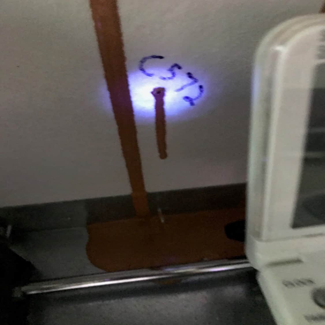
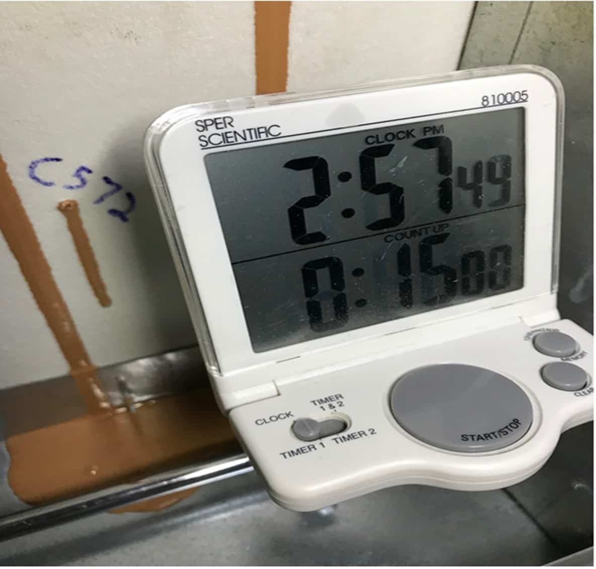
The hole was tested for 15 minutes with no evidence of water leakage under the black light used to illuminate the dye if the hole was leaking.
Figure 25. The hole was tested for 15 minutes with no evidence of water leakage under the black light used to illuminate the dye if the hole was leaking.
Figure 26.
No leakage of the seal under a water test pressure of 98 mph wind-driven rain event.
Figure 26. No leakage of the seal under a water test pressure of 98 mph wind-driven rain event.
Figure 27.
Injection of the Cat 5 through insulation with a tapered diagonally cut tip was found to be the most effective way of delivering the sealant into the hole. Twisting the nozzle 180° and pumping the caulking gun once delivered enough material to seal the hole.  Pumping the second time covered over the hole between the sheathing board and the insulation as tip was removed.
Figure 27. Injection of the Cat 5 through insulation with a tapered diagonally cut tip was found to be the most effective way of delivering the sealant into the hole. Twisting the nozzle 180° and pumping the caulking gun once delivered enough material to seal the hole. Pumping the second time covered over the hole between the sheathing board and the insulation as tip was removed.
Figure 28.
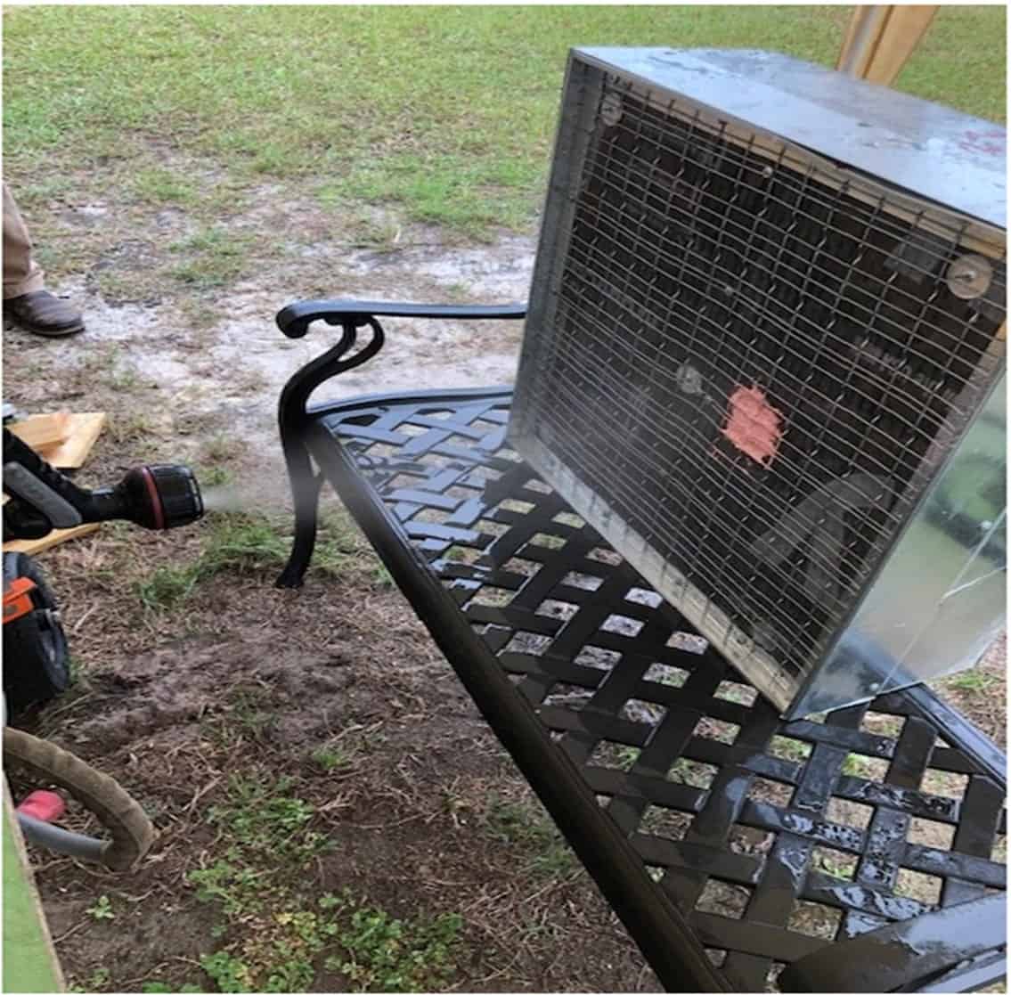
During the sealing of the holes in mockup #2 we applied a hose nozzle water test pressure between 35-40 psi for a period of 4 hours and 10 minutes. No water leakage occurred during the test.
Figure 28. During the sealing of the holes in mockup #2 we applied a hose nozzle water test pressure between 35-40 psi for a period of 4 hours and 10 minutes. No water leakage occurred during the test.

In conclusion, we believe it would be best for the industry to develop equipment to help assure proper fastener placement or for contractors to spend more time or place more focus on that. However, until that happens, the system outlined here provides a path forward where previously there was none.

chevron-logo